Tuesday, May 19, 2015

Arduino Binary Clock

How to build and control a Binary Clock on an Arduino:
by J.B. Wylzan


Project 14:  The Binary Clock
This project tells time in Binary using red, green and blue leds. The six 7-segment displays on top will be incorporated in future project to read numbers in decimal format.


Actual Binary Clock:

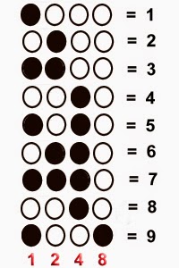
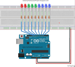
Hint: Using the block diagram below, write your sketch using the blue leds as ones or seconds. Once the leds count 9 ones, use the green leds as your tens. When you reach 60 seconds or 6 tens, use the red leds as your minutes ( 1 min = 60 sec). Once you get the idea on how to manipulate the leds just like you have been doing in our previous projects, you can now proceed to do the minutes and hours just like the clock above. You just need more leds to make it. You can also make the decimal clock (12:00:00) above by building project #20. The clock, which is actually a series of leds in figure of eight, follows the same principle. The counting is only in decimal. This tutorial also introduces the FOR loop command, a programming technique which makes longer sketches shorter.

Block Diagram:


Hardware:
9 LEDs
9 resistors 
connecting wires
breadboard
Arduino R3 UNO board

Code # 14:
/*
  iHacklab Binary Clock
  powered by Arduino
  sketched by J.B. Wylzan
  modified by Lawsinium

  Read the time using Binary 
  This example code is public domain.
 */

 // Setup pins 4 to 12
void setup() 
 {
  pinMode(4, OUTPUT);
  pinMode(5, OUTPUT);
  pinMode(6, OUTPUT);
  pinMode(7, OUTPUT);
  pinMode(8, OUTPUT);
  pinMode(9, OUTPUT);
  pinMode(10, OUTPUT);
  pinMode(11, OUTPUT);
  pinMode(12, OUTPUT);
 }
The sketch above can be written is a shorter form by using a FOR loop procedure. The two lines below is just the same as writing the longer 9 lines above. Try it!

for (int pin = 4; pin < 13; pin++) {
pinMode(pin, OUTPUT);

Challenge: Try sketching first what you have learned from Project Binary Counter step by step, progressing from seconds (blue leds) to minutes (green leds) to hours (red leds) using again the three basic commands. This is the way we become better programmers.


Actual Layout:


Procedure:
1. Use the same prototype as shown above
2. Run the Arduino Interface
3. Select File > New
4. Copy Code #14 above
5. Paste Code #14
6. Click File > Save
7. Click Verify
8. Click Upload
9. The 9 leds will count like a clock only in binary format.


Disclaimer:  We shall not be liable for any loss or damage of whatever nature - direct, indirect, consequential, or otherwise - which may arise as a result of your use of any information on this website. However, if you are interested in using any of the projects for personal or educational purposes, please inform the author by email. 

Public Domain Notice: Copyright (c) 2000. All rights reserved. This article is part of a book entitled iHackRobot. Copies are welcome to be shared or distributed publicly as long proper citations are observed. Please cite as follows: Biotronics: The Silver Species, Joey Lawsin, 1988, USA.

================================================================== 
The Homotronics® and Homodruinos® logos are registered trademarks.
Copyright Biotronics© Inc. iHackRobot®. All Rights Reserved.
Patent Pending. 2000 © ®

L.A.W.S.I.N. Educational Production
 ================================================================== 


Monday, May 18, 2015

Morse Code

How to build and control an RGB LED on an Arduino:
by J.B. Wylzan


Project 13:  Morse Code 
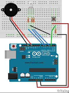
This project  shows how to control an RGB Led colors using **modular programming.

Hardware:
RGB led 
3 resistors
connecting wires
breadboard
Arduino R3 UNO board

Block Diagram:


Code # 13:

/*
  iHackLab Morse Code
  powered by Arduino
  sketched by J.B. Wylzan
  modified by Lawsinium

  The RGB LED will display the morse code for I LOVE YOU.
  This example code is public domain.
 */

int redPin = 8;
int greenPin = 7;
int bluePin = 6;

void setup()
{
  pinMode(redPin, OUTPUT);
  pinMode(greenPin, OUTPUT);
  //pinMode(bluePin, OUTPUT);
}


// .. / .-.. --- ...- . / -.-- --- ..-   <<< I LOVE YOU

void loop()
{
   dit(); dit();
     pause();
  dit(); dat(); dit(); dit();
  dat(); dat(); dat();
  dit(); dit(); dit(); dat();
  dit();
    pause();
 dat(); dit(); dat(); dat();
 dat(); dat(); dat();
 dit(); dit(); dat();
  delay(1000);
}
// ...................................................................................................................
( Only for Reference; don't add the pic on your sketch )
// ...................................................................................................................
void dit()
{
  digitalWrite(redPin , HIGH);
  delay(250);
  digitalWrite(redPin , LOW);
  delay(250);
}

void dat()
{
  digitalWrite(greenPin , HIGH);
  delay(1000);
  digitalWrite(greenPin , LOW);
  delay(250);
}

void pause()
{
  digitalWrite(bluePin, HIGH);
  delay(1000);
  digitalWrite(bluePin, LOW);
  delay(1000);
}

**Programmers Technique**

Modular Programming is one of the techniques programmers use to shorten their programs. Instead of writing very long algorithm, programs are contain into a chunk, a modular procedure. The functions dit(), dat(), and pause() are all procedures put into functional modules. This means that instead of writing all the sketch in every module inside the void loop() section, we simply use the shortcuts: dit(), dat(), and pause().

Challenge: 
1. Sketch a program using a speaker that will produce the morse code sound for I LOVE YOU.
2. Sketch a program with a push button that will mimic the morse code for I LOVE YOU.

Actual Layout:


Procedure:
1. Build the prototype as shown above
2. Run the Arduino Interface
3. Select File > New
4. Copy Code # 13 above
5. Paste Code #13
6. Click File > Save
7. Click Verify
8. Click Upload
9. The RGB led will blink on and off like a morse code.


Disclaimer:  We shall not be liable for any loss or damage of whatever nature - direct, indirect, consequential, or otherwise - which may arise as a result of your use of any information on this website. However, if you are interested in using any of the projects for personal or educational purposes, please inform the author by email. 

Public Domain Notice: Copyright (c) 2000. All rights reserved. This article is part of a book entitled iHackRobot. Copies are welcome to be shared or distributed publicly as long proper citations are observed. Please cite as follows: Biotronics: The Silver Species, Joey Lawsin, 1988, USA.

================================================================== 
The Homotronics® and Homodruinos® logos are registered trademarks.
Copyright Biotronics© Inc. iHackRobot®. All Rights Reserved.
Patent Pending. 2000 © ®

L.A.W.S.I.N. Educational Production
 ================================================================== 


Sunday, May 17, 2015

The Magic Wave Symphony

How to build and control an LED bar graph on an Arduino using a hand gesture:
by J.B. Wylzan

Project 13: Electromagnetic Emitter
This project shows how to control the led bar graph by means of the wave of a hand.


Hardware:
LEDs
resistors
switch button
wires
breadboard
computer cable
Arduino UNO

Block Diagram:


Procedure:
1. Use the same prototype as shown above
2. Run the Arduino Interface
3. Select File > New
4. Copy Code #13  below
5. Paste Code #13
6. Click File > Save
7. Click Verify
8. Click Upload
9. Activate the Led Indicators by bringing your hand near the emitter.

Code # 13:  
/* 
    iHackLab Electromagnetic Emitter
    powered by Arduino
    sketched by J.B. Wylzan
    modified by Lawsinium

  This example code is public domain. */
    
//declare variables/constants

int y = 1000;                    // y is a variable with a certain value = 1000
int x = A1                        // x is a variable with uncertain value, 0 or 1

void setup() {
  pinMode(x, INPUT);
  pinMode(4, OUTPUT);
  pinMode(5, OUTPUT);
  pinMode(6, OUTPUT);
  pinMode(7, OUTPUT);
  pinMode(8, OUTPUT);
  pinMode(9, OUTPUT);
  pinMode(10, OUTPUT);
  pinMode(11, OUTPUT);
  pinMode(12, OUTPUT);
}

void loop() {
 z = analogRead(x);                               // input action: 0 or 1
 if (z == 0)                                               // if  z == 0 
 {
 digitalWrite(8, HIGH);                          // led#8 turns ON
 }
else                                                         // if  z == 1
 {
  digitalWrite(8, LOW);                         // then led#8 turns OFF
      // **project reader starts**           // 
  digitalWrite(4, HIGH);   // turn the LED on 
  delay(500);
  digitalWrite(4, LOW);    // turn the LED off 
  
  digitalWrite(5, HIGH);   // turn the LED on
   delay(500);
  digitalWrite(5, LOW);    // turn the LED off

  digitalWrite(6, HIGH);   // turn the LED on
  delay(500);
  digitalWrite(6, LOW);    // turn the LED off
  
  digitalWrite(7, HIGH);   // turn the LED on
   delay(500); 
  digitalWrite(7, LOW);    // turn the LED off 

  digitalWrite(8, HIGH);   // turn the LED on 
  delay(500);
  digitalWrite(8, LOW);    // turn the LED off
  
  digitalWrite(9, HIGH);   // turn the LED on
  delay(500);
  digitalWrite(9, LOW);    // turn the LED off
  
  digitalWrite(10, HIGH);   // turn the LED on
  delay(500);
  digitalWrite(10, LOW);    // turn the LED off
  
  digitalWrite(11, HIGH);   // turn the LED on 
  delay(500);
  digitalWrite(11, LOW);    // turn the LED off  
  
  digitalWrite(12, HIGH);   // turn the LED on
  delay(500);
  digitalWrite(12, LOW);    // turn the LED off
       
      // **procedure Reader ends** 
  }
}

/*    End of Program       */

Project # 14: Binary Clock


Disclaimer:  We shall not be liable for any loss or damage of whatever nature - direct, indirect, consequential, or otherwise - which may arise as a result of your use of any information on this website. However, if you are interested in using any of the projects for personal or educational purposes, please inform the author by email. 

Public Domain Notice: Copyright (c) 2000. All rights reserved. This article is part of a book entitled iHackRobot. Copies are welcome to be shared or distributed publicly as long proper citations are observed. Please cite as follows: Biotronics: The Silver Species, Joey Lawsin, 1988, USA.

================================================================== 
The Homotronics® and Homodruinos® logos are registered trademarks.
Copyright Biotronics© Inc. iHackRobot®. All Rights Reserved.
Patent Pending. 2000 © ®

L.A.W.S.I.N. Educational Production
 ================================================================== 


Saturday, May 16, 2015

The Game of Reflex

How to build a Game of Reflex on an Arduino using two switch buttons:
by J.B. Wylzan


Project 12: The Game of Reflex
This is a physics game about reaction time. The first one who presses the button and turns on the set of leds wins the game.


Block Diagram:
Image provided by Fritzing
Hardware:
LEDs
resistors
switch buttons
wires
breadboard
computer cable
Arduino UNO

Actual Assembly:  


Procedure:
1. Use the same prototype as shown above
2. Run the Arduino Interface
3. Select File > New
4. Copy Code #12  below
5. Paste Code #12
6. Click File > Save
7. Click Verify
8. Click Upload
9. Activate a set of Leds using either switch A or switch B

Code # 12:  
/*
  iHackLab Game of Impulse
  powered by Arduino
  sketched by J.B. Wylzan
  modified by Lawsinium

  Turns a set of Leds using either switch A or switch B
  This example code is public domain.
 */

 // Setup pins 3 to 11 as output; 2 and12 as inputs
void setup() 
 {
  pinMode(2, INPUT_PULLUP);
  pinMode(12, INPUT_PULLUP);
  pinMode(3, OUTPUT);
  pinMode(4, OUTPUT);
  pinMode(5, OUTPUT);
  pinMode(6, OUTPUT);
  pinMode(7, OUTPUT);
  pinMode(8, OUTPUT);
  pinMode(9, OUTPUT);
  pinMode(10, OUTPUT);
  pinMode(11, OUTPUT);
 }

// Procedure to turn a set of leds using either button A or button B
void loop() {
if (digitalRead(2) == 0) {
  digitalWrite(4, HIGH);   // turn the LED on 
  digitalWrite(5, HIGH);   // turn the LED on 
  digitalWrite(6, HIGH);   // turn the LED on 
  digitalWrite(7, HIGH);   // turn the LED on 
  digitalWrite(9, LOW);   // turn the LED on
  digitalWrite(10, LOW);   // turn the LED on
  digitalWrite(11, LOW);   // turn the LED on
  digitalWrite(3, LOW);   // turn the LED on
}
else
{
  if (digitalRead(12) == 0) {
  digitalWrite(4, LOW);   // turn the LED on 
  digitalWrite(5, LOW);   // turn the LED on 
  digitalWrite(6, LOW);   // turn the LED on 
  digitalWrite(7, LOW);   // turn the LED on 
  digitalWrite(9, HIGH);   // turn the LED on
  digitalWrite(10, HIGH);   // turn the LED on
  digitalWrite(11, HIGH);   // turn the LED on
  digitalWrite(3, HIGH);   // turn the LED on
   }
}
}

/*    End of Program       */


Project # 13: The Wave Symphony


Disclaimer:  We shall not be liable for any loss or damage of whatever nature - direct, indirect, consequential, or otherwise - which may arise as a result of your use of any information on this website. However, if you are interested in using any of the projects for personal or educational purposes, please inform the author by email. 

Public Domain Notice: Copyright (c) 2000. All rights reserved. This article is part of a book entitled iHackRobot. Copies are welcome to be shared or distributed publicly as long proper citations are observed. Please cite as follows: Biotronics: The Silver Species, Joey Lawsin, 1988, USA.

================================================================== 
The Homotronics® and Homodruinos® logos are registered trademarks.
Copyright Biotronics© Inc. iHackRobot®. All Rights Reserved.
Patent Pending. 2000 © ®

L.A.W.S.I.N. Educational Production
 ================================================================== 

RGB LED

How to build and control an RGB LED on an Arduino:
by J.B. Wylzan


Project 21:  RGB LED 

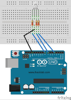
This project  shows how to control a RGB Led colors. 
These colors will be used as ROM indicators as we build our Homotronics robots.

Hardware:
RGB led 
2 resistors
connecting wires
breadboard
Arduino R3 UNO board

Block Diagram:


Code # 21:

/*
  iHackLab RGB Colors
  powered by Arduino
  sketched by J.B. Wylzan
  modified by Lawsinium

  The RGB LED will display the colors red, green and blue continuously.
  This example code is public domain.
 */

int redPin = 8;
int greenPin = 7;
int bluePin = 4;
void setup()
{
  pinMode(redPin, OUTPUT);
  pinMode(greenPin, OUTPUT);
  pinMode(bluePin, OUTPUT);
}

void loop()
{
  digitalWrite(redPin, HIGH);                                   // red led
  digitalWrite(greenPin, LOW);
  digitalWrite(bluePin, LOW);
  delay(1000);

  digitalWrite(redPin, LOW);                                   // green led
  digitalWrite(greenPin, HIGH);
  digitalWrite(bluePin, LOW);
  delay(1000);

  digitalWrite(redPin, LOW);                                  // blue led
  digitalWrite(greenPin, LOW);
  digitalWrite(bluePin, HIGH);
  delay(1000);
}

Challenge: 
Sketch a program that will produce other colors aside from red, green and blue by altering or combining HIGH or LOW inside digitalWrite(). Be surprised what colors will be created. Use the programming procedure technique below to create various colors by replacing r, g, and b with any numbers from 0 to 255. Happy painting ;-).

void displayRGB(int r, int g, int b)
{
  analogWrite(redPin, r);
  analogWrite(greenPin, g);
  analogWrite(bluePin, b);
}


Actual Layout:


Procedure:
1. Build the prototype as shown above
2. Run the Arduino Interface
3. Select File > New
4. Copy Code # 21 above
5. Paste Code #21
6. Click File > Save
7. Click Verify
8. Click Upload
9. The RGB led will change colors from Red, Green and Blue.


Disclaimer:  We shall not be liable for any loss or damage of whatever nature - direct, indirect, consequential, or otherwise - which may arise as a result of your use of any information on this website. However, if you are interested in using any of the projects for personal or educational purposes, please inform the author by email. 

Public Domain Notice: Copyright (c) 2000. All rights reserved. This article is part of a book entitled iHackRobot. Copies are welcome to be shared or distributed publicly as long proper citations are observed. Please cite as follows: Biotronics: The Silver Species, Joey Lawsin, 1988, USA.

================================================================== 
The Homotronics® and Homodruinos® logos are registered trademarks.
Copyright Biotronics© Inc. iHackRobot®. All Rights Reserved.
Patent Pending. 2000 © ®

L.A.W.S.I.N. Educational Production
 ==================================================================