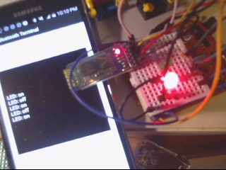
How to pair HC-05 Bluetooth on an Arduino with an Android phone:
by J.B. Wylzan
Hardware:
microservo SG90
connecting wires
breadboard
Arduino R3 UNO board
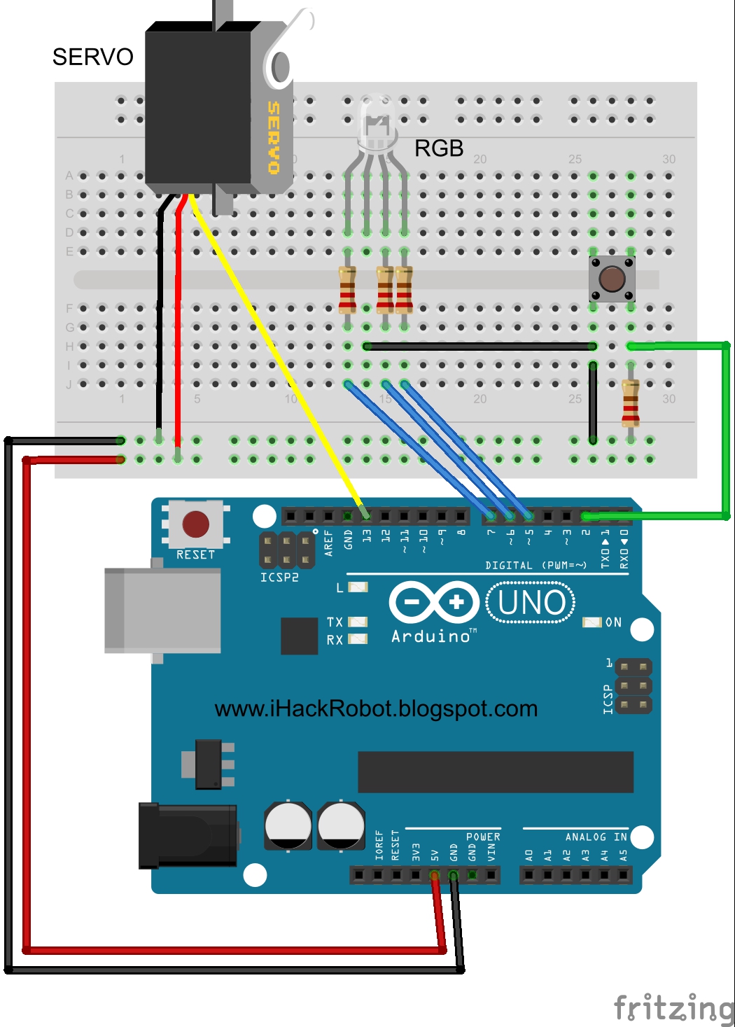
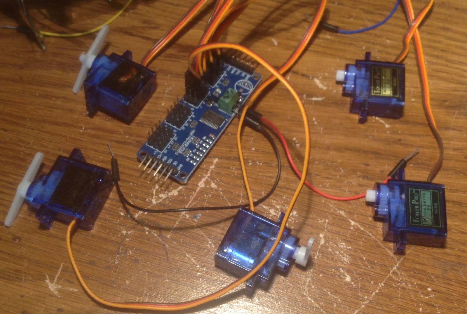
Block Diagram:

NOTE: The RGB and the Push Button are not on the sketch below. However using your understanding on our previous lessons or projects, you can add them on your sketch. Good Luck ;-)
Code # 22:
/* ===============================================================by J.B. Wylzan
Project 25: Microservo SG90
This project shows how to control the microservo from 0 to 180 degrees.

Hardware:
microservo SG90
connecting wires
breadboard
Arduino R3 UNO board
Block Diagram:
Project # 27: Microservo SG90
Author: J. B. Wylzan with some help from the Arduino community
Website: http://www.ihacklab.blogspot.com
Abstract: This project shows how to activate a servo
================================================================== */
#include <servo .h>
int x = 1000
Servo servo; // name the Servo
void setup()
{
servo.attach(6); // servo pin to arduino pin 6
}
void loop()
{
servo.write(90); // Turn servo back to 90 center position
delay(x); // Wait 1 second
servo.write(45); // Turn servo Left to 45 degrees
delay(x); // Wait 1 second
servo.write(90); // Turn servo back to center position
delay(x); // Wait 1 second
servo.write(135); // Turn servo Right to 135 degrees
delay(x); // Wait 1 second
servo.write(0); // Turn servo Left to 0 degrees
delay(x); // Wait 1 second
servo.write(180); // Turn servo Right to 180 degrees
delay(x); // Wait 1 second
}
Challenge:
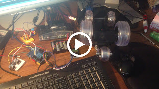
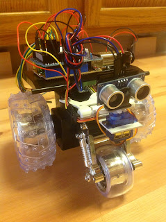
Create the robot below using the microservo with an ultrasonic sensor attached on its axle.

Procedure:
1. Build the prototype as shown above
2. Run the Arduino Interface
3. Select File > New
4. Copy Code #22 above
5. Paste Code #22
6. Click File > Save
7. Click Verify
8. Click Upload
9. Servo will scan from 0 to 180 degrees.
Serial Monitor Test:
int servopin=9;
int myangle;
int pulsewidth;
int val;
void servopulse(int servopin,int myangle)
{
pulsewidth=(myangle*11)+500; // convert angle to 500-2480 pulse width
digitalWrite(servopin,HIGH); // set the level of servo pin as “high”
delayMicroseconds(pulsewidth); // delay microsecond of pulse width
digitalWrite(servopin,LOW); // set the level of servo pin as “low”
delay(20-pulsewidth/1000);
}
void setup()
{
pinMode(servopin,OUTPUT);
Serial.begin(9600);
Serial.println("servo ready" ) ;
}
void loop() {
val=Serial.read();
if(val>'0'&&val<='9')
{
val=val-'0'; // convert character to number
val=val*(180/9); // convert number to angle
Serial.print("servo angle: ");
Serial.print(val,DEC);
Serial.println();
for(int i=0;i<=50;i++)
{
servopulse(servopin,val);
}
}
}


Disclaimer: We shall not be liable for any loss or damage of whatever nature - direct, indirect, consequential, or otherwise - which may arise as a result of your use of any information on this website.
Public Domain Notice: Copyright (c) 2000. All rights reserved. This article is part of a book entitled iHackRobot. Copies are welcome to be shared or distributed publicly as long proper citations are observed. Please cite as follows: Biotronics: The Silver Species, Joey Lawsin, 1988, USA.
==================================================================
Patent Pending. 2000 © ®
A L.A.W.S.I.N. Educational Production