Thursday, September 24, 2015

Arduino Joystick with Led Matrix Display

How to setup a Led Matrix Display on an Arduino controlled by a joystick:
by J.B. Wylzan

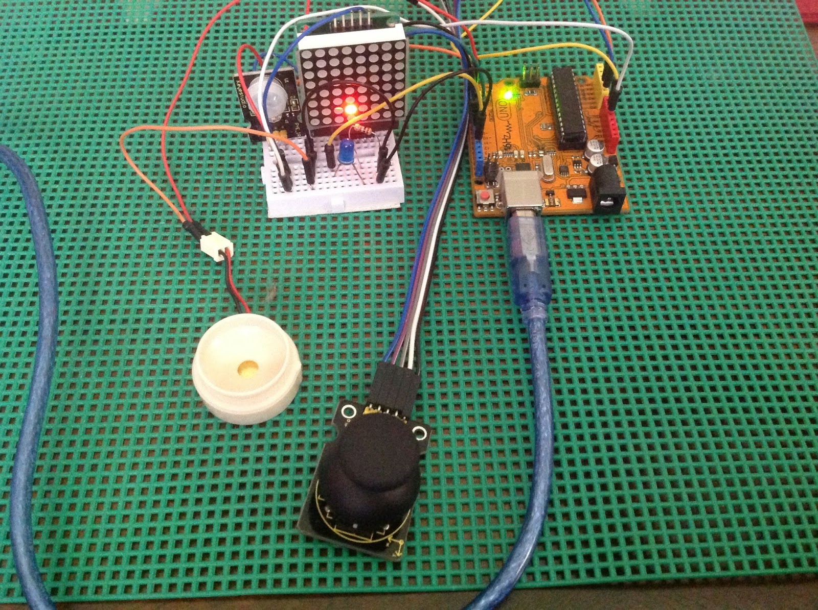
Project 33:  Joystick controls a Led Matrix Display

This project challenges the maker to incorporate a motion detector sensor,
a speaker, and a joystick that controls a led matrix display.


Hardware:
1 PIR Motion Sensor
1 Led (indicator)
1 joystick
1 speaker
1 Led Matrix Display
connecting wires
breadboard
Arduino R3 UNO board


Connection Pins:

 DataPin, din = 12;
 LatchPin, cs  = 10;
 ClockPin, clk = 11;
 Speaker= 4;               
 Led = 13;                
 Motion Sensor, S = 5;
 Joystick x,y = A0, A1;
 Vcc, +   = 5V;
 Gnd, -   = ground;


Sample Sketch for PIR and Matrix Display :

/*
  iHacklab Led Matrix Display controlled by a joystick
  This sketch does the following procedures:
1. Buzzer when motion is detected
2. Display graphix when there is no motion detected.
3. Joystick controls an led in a matrix display
4. Circuit connections embedded 
 */

#include "LedControl.h"

int DataPin = 12;
int LatchPin = 10;
int ClockPin = 11;
LedControl lc=LedControl(12,11,10,1);
int spkr = 4;               
int led = 13;                
int sensor = 5;             
int state = LOW;            
int val = 0;                 
int pos = 0;
int  var = 0;


void setup() {
  pinMode(led, OUTPUT);      // initalize LED as an output
 pinMode(spkr, OUTPUT);      // initalize speaker as an output
  pinMode(sensor, INPUT);    // initialize sensor as an input
 
  lc.shutdown(0, false);
  lc.setIntensity(0, 5);
  lc.clearDisplay(0);

  delayMicroseconds(30);
}

void loop(){
  val = digitalRead(sensor);   // read sensor value
  if (val == HIGH) {           // check if the sensor is HIGH
    Serial.println("Motion detected!");
 while(var < 5) {       
        digitalWrite(13, HIGH);
        delay(1000);
       digitalWrite(13, LOW);
       delay(1000);
       tone(4, 440, 200);
      var++;
       }
   var=0;
  
    if (state == LOW) {
      digitalWrite(led, HIGH);   // turn LED ON
      state = HIGH;       // update variable state to HIGH
    }
  }
  else {
      digitalWrite(led, LOW); // turn LED OFF
      delay(200);             // delay 200 milliseconds
      rain();
    //  block();
      if (state == HIGH){
        Serial.println("Motion stopped!");
        state = LOW;       // update variable state to LOW
        
    }
  }
}


void rain()
  {
  for (int row=0; row<8; row++)
  {
    for (int col=0; col<8; col++)
    {
      lc.setLed(0,col,row,true); // turns on LED at col, row
      delay(100);
    lc.setLed(0,col,row,false); // turns on LED at col, row
    }
  }
  }

void block(){
    for (int row=0; row<8; row++)
  {
    for (int col=7; col<8; col++)
    {
      lc.setLed(0,col,row,true); // turns on LED at col, row
      delay(100);
      digitalWrite(4, LOW);
     
    }
  }
 }

  
Sample sketch for Joystick/Matrix:


#include "LedControl.h"
int A0 = 0;  //x
int A1 = 1;  //y
int Zkey = 3;    //z

LedControl lc=LedControl(12,11,10,1);


void setup() {
  Serial.begin(9600);
  pinMode(z,input);
  lc.shutdown(0,false);
  lc.setIntensity(0,5);
  lc.clearDisplay(0);

}

void loop() {
INT X,Y,Z 
  X= analogRead(A0);
  Y= analogRead(A1);
  Z =digitalRead(Zkey)
  char x = map(X, 1021, 0, 0, 7);
  char y = map(Y, 1021, 0, 7, 0);
 

  Serial.print(X, DEC);
  Serial.print(",");
  Serial.print(Y, DEC);
  Serial.print(",");
  Serial.print(Z, DEC);

    lc.clearDisplay(0);
    lc.setLed(0,x,y,true); 
    delay(100);
}


Disclaimer:  We shall not be liable for any loss or damage of whatever nature - direct, indirect, consequential, or otherwise - which may arise as a result of your use of any information on this website. However, if you are interested in using any of the projects for personal or educational purposes, please inform the author by email. 

Public Domain Notice: Copyright (c) 2000. All rights reserved. This article is part of a book entitled iHackRobot. Copies are welcome to be shared or distributed publicly as long proper citations are observed. Please cite as follows: Biotronics: The Silver Species, Joey Lawsin, 1988, USA.

================================================================== 
The Homotronics® and Homodruinos® logos are registered trademarks.
Copyright Biotronics© Inc. iHackRobot®. All Rights Reserved.
Patent Pending. 2000 © ®

L.A.W.S.I.N. Educational Production
 ================================================================== 


Friday, September 11, 2015

Arduino Radar

How to setup a SG90 Mircoservo on an Arduino with an ultrasonic sensor:
by J.B. Wylzan 

Project 25:  Radar Scanner Display
This project shows how objects are detected and displayed on your computer screen imitating a radar monitor. A separate software called Processing 3.0a10 was used to interact with the Arduino R3 IDE.


Hardware:
Microservo SG90
Ultrasonic Sensor
connecting wires
breadboard
Arduino R3 UNO board

Code # 25:
/*
  iHacklab Radar Monitor Display
  This project, inspired by Dejan Nedelkovski,
  was modified to fit the display into a standard computer monitor

  reprogrammed by JBWylzan
  
  Using Graphics Interface provided by Processsing 3.0
  The example code is public domain */

import processing.serial.*;  
import java.awt.event.KeyEvent;  
import java.io.IOException;

Serial myPort;  
String angle="";
String distance="";
String data="";
String noObject;
float pixsDistance;
int iAngle, iDistance;
int index1=0;
int index2=0;

void setup() {
 size (1000, 500);  
 smooth();
 myPort = new Serial(this,"COM4", 9600);  
 myPort.bufferUntil('.');  
}

void draw() {
  fill(98,245,31);
  noStroke();
  fill(0,4); 
  rect(0, 0, width, 1010); 
  fill(98,245,31); // green 
  drawRadar(); 
  drawLine();
  drawObject();
  drawText();
}

void serialEvent (Serial myPort) { 
  data = myPort.readStringUntil('.');
  data = data.substring(0,data.length()-1);
  index1 = data.indexOf(","); 
  angle= data.substring(0, index1); 
  distance= data.substring(index1+1, data.length()); 
  iAngle = int(angle);
  iDistance = int(distance);
}

void drawRadar() {
  pushMatrix();
  translate(500,480); 
  noFill();
  strokeWeight(2);
  stroke(98,245,31);
  arc(0,0,1000,1000,PI,TWO_PI);
    arc(0,0,800,800,PI,TWO_PI);
  arc(0,0,600,600,PI,TWO_PI);
  arc(0,0,400,400,PI,TWO_PI);
  arc(0,0,200,200,PI,TWO_PI);
  line(-500,0,500,0);
  line(0,0,-500*cos(radians(30)),-500*sin(radians(30)));
  line(0,0,-500*cos(radians(60)),-500*sin(radians(60)));
  line(0,0,-500*cos(radians(90)),-500*sin(radians(90)));
  line(0,0,-500*cos(radians(120)),-500*sin(radians(120)));
  line(0,0,-500*cos(radians(150)),-500*sin(radians(150)));
  line(-500*cos(radians(30)),0,500,0);
  popMatrix();
}

void drawObject() {
  pushMatrix();
  translate(500,480); 
  strokeWeight(9);
  stroke(255,10,10); // red 
  pixsDistance = iDistance*22.5; 
  if(iDistance<30){
  line(pixsDistance*cos(radians(iAngle)),-pixsDistance*sin(radians(iAngle)),500*cos(radians(iAngle)),-500*sin(radians(iAngle)));
  }
  popMatrix();
}

void drawLine() {
  pushMatrix();
  strokeWeight(9);
  stroke(30,250,60);
  translate(500,480); 
  line(0,0,500*cos(radians(iAngle)),-500*sin(radians(iAngle))); 
  popMatrix();
}

void drawText() { 
  pushMatrix();
  textSize(14);
  fill(98,245,60);
  translate(500,490);
  text("90°",0,5);
  text("www.iHackLab.blogspot.com        0°",250,5);
  text("180°",-500,5);
  popMatrix(); 
}


Challenge: 
Use the sketch above and your previous projects on Servo and Ultrasonic to detect objects and monitor them on a radar-like screen display. 

Actual Layout:


Procedure:
1. Build the prototype as shown above
2. Run the Processing Interface
3. Select File > New
4. Copy Code #25 above
5. Paste Code #25
6. Click File > Save
7. Click Run
8. Wait for the Screen to display
9. Open previous projects on ultrasonic or servo
10. Upload sketch and run your hands on the ultrasonic


Disclaimer:  We shall not be liable for any loss or damage of whatever nature - direct, indirect, consequential, or otherwise - which may arise as a result of your use of any information on this website. However, if you are interested in using any of the projects for personal or educational purposes, please inform the author by email. 

Public Domain Notice: Copyright (c) 2000. All rights reserved. This article is part of a book entitled iHackRobot. Copies are welcome to be shared or distributed publicly as long proper citations are observed. Please cite as follows: Biotronics: The Silver Species, Joey Lawsin, 1988, USA.

================================================================== 
The Homotronics® and Homodruinos® logos are registered trademarks.
Copyright Biotronics© Inc. iHackRobot®. All Rights Reserved.
Patent Pending. 2000 © ®

L.A.W.S.I.N. Educational Production
 ==================================================================