Thursday, July 30, 2015

Arduino Sound Generator

How to build a Sound Generator on an Arduino: 
by J.B. Wylzan


Project 20:  Sound Generator
This project  uses a piezo speaker to generate musical tones. 


Hardware:
piezo speaker (hacked from a toy alarm)
resistor
connecting wires
breadboard
Arduino R3 UNO board

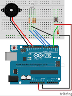
Block Diagram:


NOTE: The RGB and the Push Button are not on the sketch below. However referring to project RGB and project Switch Button you can both combine them on this project. Good Luck ;-)

Code # 20:

/*
  iHackLab Piezo Speaker
  powered by Arduino
  modified by Lawsinium

  This example code is public domain.
 */

int speakerPin = 3;
int numNotes = 8;
int notes[] = {262, 294, 330, 349, 392, 440, 494, 523};
//    middle C   Do   Re   Mi    Fa    So    La    Ti    Do

void setup()
{
  pinMode(speakerPin, OUTPUT);
}

void loop()
{
   for (int i = 0; i < numNotes; i++)
  {
    tone(speakerPin, notes[i]);
    delay(500);
  }
  noTone(speakerPin);
}

// Sketch ends here

- - - - - - - - - - - - - - - - - - - - - - - - -
/* Here is another example:
 timeHigh = period / 2 = 1 / (2 * toneFrequency)
*/

int speakerPin = 9;

int length = 15; // the number of notes
char notes[] = "ccggaagffeeddc "; // a space represents a rest
int beats[] = { 1, 1, 1, 1, 1, 1, 2, 1, 1, 1, 1, 1, 1, 2, 4 };
int tempo = 300;

void playTone(int tone, int duration) {
  for (long i = 0; i < duration * 1000L; i += tone * 2) {
    digitalWrite(speakerPin, HIGH);
    delayMicroseconds(tone);
    digitalWrite(speakerPin, LOW);
    delayMicroseconds(tone);
  }
}

void playNote(char note, int duration) {
  char names[] = { 'c', 'd', 'e', 'f', 'g', 'a', 'b', 'C' };
  int tones[] = { 1915, 1700, 1519, 1432, 1275, 1136, 1014, 956 };

  // play the tone corresponding to the note name
  for (int i = 0; i < 8; i++) {
    if (names[i] == note) {
      playTone(tones[i], duration);
    }
  }
}

void setup() {
  pinMode(speakerPin, OUTPUT);
}

void loop() {
  for (int i = 0; i < length; i++) {
    if (notes[i] == ' ') {
      delay(beats[i] * tempo); // rest
    } else {
      playNote(notes[i], beats[i] * tempo);
    }

    // pause between notes
    delay(tempo / 2); 
  }
}
 
- - - - - - - - - - - - - - - - -  - 


*************************************************
FOR FUTURE REFERENCE :

To add the library Pitches, Open the the arrow just below the serial monitor and select "New Tab", Paste the sketch below, and Save with a filename pitches.h.

/*************************************************
 * Public Constants
 *************************************************/

#define NOTE_B0  31
#define NOTE_C1  33
#define NOTE_CS1 35
#define NOTE_D1  37
#define NOTE_DS1 39
#define NOTE_E1  41
#define NOTE_F1  44
#define NOTE_FS1 46
#define NOTE_G1  49
#define NOTE_GS1 52
#define NOTE_A1  55
#define NOTE_AS1 58
#define NOTE_B1  62
#define NOTE_C2  65
#define NOTE_CS2 69
#define NOTE_D2  73
#define NOTE_DS2 78
#define NOTE_E2  82
#define NOTE_F2  87
#define NOTE_FS2 93
#define NOTE_G2  98
#define NOTE_GS2 104
#define NOTE_A2  110
#define NOTE_AS2 117
#define NOTE_B2  123
#define NOTE_C3  131
#define NOTE_CS3 139
#define NOTE_D3  147
#define NOTE_DS3 156
#define NOTE_E3  165
#define NOTE_F3  175
#define NOTE_FS3 185
#define NOTE_G3  196
#define NOTE_GS3 208
#define NOTE_A3  220
#define NOTE_AS3 233
#define NOTE_B3  247
#define NOTE_C4  262
#define NOTE_CS4 277
#define NOTE_D4  294
#define NOTE_DS4 311
#define NOTE_E4  330
#define NOTE_F4  349
#define NOTE_FS4 370
#define NOTE_G4  392
#define NOTE_GS4 415
#define NOTE_A4  440
#define NOTE_AS4 466
#define NOTE_B4  494
#define NOTE_C5  523
#define NOTE_CS5 554
#define NOTE_D5  587
#define NOTE_DS5 622
#define NOTE_E5  659
#define NOTE_F5  698
#define NOTE_FS5 740
#define NOTE_G5  784
#define NOTE_GS5 831
#define NOTE_A5  880
#define NOTE_AS5 932
#define NOTE_B5  988
#define NOTE_C6  1047
#define NOTE_CS6 1109
#define NOTE_D6  1175
#define NOTE_DS6 1245
#define NOTE_E6  1319
#define NOTE_F6  1397
#define NOTE_FS6 1480
#define NOTE_G6  1568
#define NOTE_GS6 1661
#define NOTE_A6  1760
#define NOTE_AS6 1865
#define NOTE_B6  1976
#define NOTE_C7  2093
#define NOTE_CS7 2217
#define NOTE_D7  2349
#define NOTE_DS7 2489
#define NOTE_E7  2637
#define NOTE_F7  2794
#define NOTE_FS7 2960
#define NOTE_G7  3136
#define NOTE_GS7 3322
#define NOTE_A7  3520
#define NOTE_AS7 3729
#define NOTE_B7  3951
#define NOTE_C8  4186
#define NOTE_CS8 4435
#define NOTE_D8  4699
#define NOTE_DS8 4978

Challenge: 
1. Write a simple sketch that will turn On and Off each Led as each note plays.
2. Write a sketch that will turn on the whole project using a switch button.
3. Try different Octave (see musical image above)

Actual Layout:


Procedure:
1. Build the prototype as shown above
2. Run the Arduino Interface
3. Select File > New
4. Copy Code # 20 above
5. Paste Code #20
6.. Click File > Save
7.. Click Verify
8. Click Upload
9. The speaker will play the do-re-mi tune.


Disclaimer:  We shall not be liable for any loss or damage of whatever nature - direct, indirect, consequential, or otherwise - which may arise as a result of your use of any information on this website. However, if you are interested in using any of the projects for personal or educational purposes, please inform the author by email. 

Public Domain Notice: Copyright (c) 2000. All rights reserved. This article is part of a book entitled iHackRobot. Copies are welcome to be shared or distributed publicly as long proper citations are observed. Please cite as follows: Biotronics: The Silver Species, Joey Lawsin, 1988, USA.

================================================================== 
The Homotronics® and Homodruinos® logos are registered trademarks.
Copyright Biotronics© Inc. iHackRobot®. All Rights Reserved.
Patent Pending. 2000 © ®

L.A.W.S.I.N. Educational Production
 ================================================================== 


Saturday, July 4, 2015

7-Segment LED Display

How to build and control a 7 segment LED counter on an Arduino:
by J.B. Wylzan


Project :  7-Segment LED Counter
This project  shows how to control a 7-Segment Led Display.
  The 7-segment display is actually like the train of LEDs found on our previous projects. The only difference is the leds are now formed in a figure of eight(8) instead.


Hardware:
7-segment led display
connecting wires
breadboard
Arduino R3 UNO board

Schematic Diagram:
Block Diagram:


Code # 20:

/*
  iHackLab 7-Segment Counter
  powered by Arduino
  sketched by J.B. Wylzan
  modified by Lawsinium

  The 7-segment display will count from 0 to 9 .
  This example code is public domain.
 */

int A =4;
int B =5;
int C =6;
int D= 7;
int E =8;
int F =9;
int G= 10;
int H= 11;
int x = 1000;

void setup()
{
  //Setup our pins
  pinMode(A, OUTPUT);
  pinMode(B, OUTPUT);
  pinMode(C, OUTPUT);
  pinMode(D, OUTPUT);
  pinMode(E, OUTPUT);
  pinMode(F, OUTPUT);
  pinMode(G, OUTPUT);
  pinMode(H, OUTPUT);
}

void loop()
{
   zero();
  delay(x);
   one();
  delay(x);
  two();
    delay(x);
  three();
    delay(x);
  four();
    delay(x);
  five();
    delay(x);
  six();
    delay(x);
  seven();
    delay(x);
  eight();
    delay(x);
  nine();
    delay(x);
}

void zero()
{
  digitalWrite(A, LOW);
  digitalWrite(B, LOW);
  digitalWrite(C, LOW);
  digitalWrite(D, LOW);
  digitalWrite(E, LOW);
  digitalWrite(F, LOW);
  digitalWrite(G, HIGH);
  digitalWrite(H, LOW);
}

void one()
{
  digitalWrite(A, HIGH);
  digitalWrite(B, HIGH);
  digitalWrite(C, HIGH);
  digitalWrite(D, HIGH);
  digitalWrite(E, LOW);
  digitalWrite(F, LOW);
  digitalWrite(G, HIGH);
  digitalWrite(H, LOW);
}

void two()
{
  digitalWrite(A, LOW);
  digitalWrite(B, LOW);
  digitalWrite(C, HIGH);
  digitalWrite(D, LOW);
  digitalWrite(E, LOW);
  digitalWrite(F, HIGH);
  digitalWrite(G, LOW);
  digitalWrite(H, LOW);
}

void three()
{
  digitalWrite(A, LOW);
  digitalWrite(B, LOW);
  digitalWrite(C, LOW);
  digitalWrite(D, LOW);
  digitalWrite(E, HIGH);
  digitalWrite(F, HIGH);
  digitalWrite(G, LOW);
  digitalWrite(H, LOW);
}

void four()
{
  digitalWrite(A, HIGH);
  digitalWrite(B, LOW);
  digitalWrite(C, LOW);
  digitalWrite(D, HIGH);
  digitalWrite(E, HIGH);
  digitalWrite(F, LOW);
  digitalWrite(G, LOW);
  digitalWrite(H, LOW);
}

void five()
{
  digitalWrite(A, LOW);
  digitalWrite(B, HIGH);
  digitalWrite(C, LOW);
  digitalWrite(D, LOW);
  digitalWrite(E, HIGH);
  digitalWrite(F, LOW);
  digitalWrite(G, LOW);
  digitalWrite(H, LOW);
}

void six()
{
  digitalWrite(A, LOW);
  digitalWrite(B, HIGH);
  digitalWrite(C, LOW);
  digitalWrite(D, LOW);
  digitalWrite(E, LOW);
  digitalWrite(F, LOW);
  digitalWrite(G, LOW);
  digitalWrite(H, LOW);
}

void seven()
{
  digitalWrite(A, LOW);
  digitalWrite(B, LOW);
  digitalWrite(C, LOW);
  digitalWrite(D, HIGH);
  digitalWrite(E, HIGH);
  digitalWrite(F, HIGH);
  digitalWrite(G, HIGH);
  digitalWrite(H, LOW);
}

void eight()
{
  digitalWrite(A, LOW);
  digitalWrite(B, LOW);
  digitalWrite(C, LOW);
  digitalWrite(D, LOW);
  digitalWrite(E, LOW);
  digitalWrite(F, LOW);
  digitalWrite(G, LOW);
  digitalWrite(H, LOW);
}

void nine()
{
  digitalWrite(A, LOW);
  digitalWrite(B, LOW);
  digitalWrite(C, LOW);
  digitalWrite(D, LOW);
  digitalWrite(E, HIGH);
  digitalWrite(F, LOW);
  digitalWrite(G, LOW);
  digitalWrite(H, LOW);
}

Challenge: 
Sketch a program wherein the 7-segment counter displays the alphabet.


Actual Layout:


Procedure:
1. Build the prototype as shown above
2. Run the Arduino Interface
3. Select File > New
4. Copy Code # 20 above
5. Paste Code #20
6. Click File > Save
7. Click Verify
8. Click Upload
9. The 7-segment display will count from 0 to 9..


Disclaimer:  We shall not be liable for any loss or damage of whatever nature - direct, indirect, consequential, or otherwise - which may arise as a result of your use of any information on this website. However, if you are interested in using any of the projects for personal or educational purposes, please inform the author by email. 

Public Domain Notice: Copyright (c) 2000. All rights reserved. This article is part of a book entitled iHackRobot. Copies are welcome to be shared or distributed publicly as long proper citations are observed. Please cite as follows: Biotronics: The Silver Species, Joey Lawsin, 1988, USA.

================================================================== 
The Homotronics® and Homodruinos® logos are registered trademarks.
Copyright Biotronics© Inc. iHackRobot®. All Rights Reserved.
Patent Pending. 2000 © ®

L.A.W.S.I.N. Educational Production
 ================================================================== 


Wednesday, July 1, 2015

Keyboard Controlled Lights

How to build and control an LED on an Arduino using a keyboard:
by J.B. Wylzan


Project 19:  Keyboard controlled LED
This project turns On and Off  an Led using a keyboard thru the Arduino Serial Monitor.


Block Diagram:


Hardware:
1 Keyboard
1 led
1 resistor
connecting wires
breadboard
Arduino R3 UNO board
Arduino Serial Monitor

Code # 19:
/*
  iHacklab Keyboard Controlled Led
  powered by Arduino

  Turns On and Off  an Led using the keyboard and Arduino Serial Monitor
  The example code is public domain.
 */

int ledPin = 8; 
int state = 0;
int flag = 0; 

void setup() {
 pinMode(ledPin, OUTPUT);
 digitalWrite(ledPin, LOW);
 Serial.begin(9600);                         //  Setup Serial Monitor
}

void loop() {

 if(Serial.available() > 0){
 state = Serial.read();
 flag=0;
 }

 if (state == '0') {
 digitalWrite(ledPin, LOW);
 if(flag == 0){
 Serial.println("LED: off");
 flag = 1;
 }
 }

 else if (state == '1') {
 digitalWrite(ledPin, HIGH);
 if(flag == 0){
 Serial.println("LED: on");
 flag = 1;
 }
 }
}

// end of the sketch

New Command: Serial.Println


Challenge: 
Use the keyboard to light up 4 leds and display each status in the arduino serial monitor.

Actual Layout:


Procedure:
1. Build the prototype as shown above
2. Run the Arduino Interface
3. Select File > New
4. Copy Code #19 above
5. Paste Code #19
6. Click File > Save
7. Click Verify
8. Click Upload
9. Open the Serial Monitor
10. Type 1 to turn on the Led
11. Type 0 to turn off the Led


Project # 21:  Motorshield L239D


Disclaimer:  We shall not be liable for any loss or damage of whatever nature - direct, indirect, consequential, or otherwise - which may arise as a result of your use of any information on this website. However, if you are interested in using any of the projects for personal or educational purposes, please inform the author by email. 

Public Domain Notice: Copyright (c) 2000. All rights reserved. This article is part of a book entitled iHackRobot. Copies are welcome to be shared or distributed publicly as long proper citations are observed. Please cite as follows: Biotronics: The Silver Species, Joey Lawsin, 1988, USA.

================================================================== 
The Homotronics® and Homodruinos® logos are registered trademarks.
Copyright Biotronics© Inc. iHackRobot®. All Rights Reserved.
Patent Pending. 2000 © ®

L.A.W.S.I.N. Educational Production
 ==================================================================