How to build a Binary Counter on an Arduino:
by J.B. Wylzan
Project 7: Binary Counter:
This project teaches you how to count in Binary.
Four LEDs - yellow, green, red, blue - are used as a binary counter.
The binary and decimal clock below will be your final project as we progress.


Hardware:
4 LEDs
4 resistors, 200 ohms
connecting wires
breadboard
computer cable
Arduino UNO
Schematic Diagram:
 |
| image created by fritzing |
Block Diagram:
 |
| image created by fritzing |
/*
iHackLab Binary Counter
powered by Arduino
sketched by J.B. Wylzan
modified by Lawsinium
Four Leds will count in Binary .
This example code is public domain.
*/
// Setup pins 4 to 12
void setup()
{
pinMode(4, OUTPUT);
pinMode(5, OUTPUT);
pinMode(6, OUTPUT);
pinMode(7, OUTPUT);
pinMode(8, OUTPUT);
pinMode(9, OUTPUT);
pinMode(10, OUTPUT);
pinMode(11, OUTPUT);
pinMode(12, OUTPUT);
pinMode(13, OUTPUT);
}
// Count Binary from 1 to 9
void loop()
{
digitalWrite(4, HIGH); // count 0ne
delay(1000);
digitalWrite(4, LOW);
delay(1000);
digitalWrite(5, HIGH); // count Two
delay(1000);
digitalWrite(5, LOW);
delay(1000);
digitalWrite(4, HIGH); // count Three
digitalWrite(5, HIGH);
delay(1000);
digitalWrite(4, LOW);
digitalWrite(5, LOW);
delay(1000);
digitalWrite(6, HIGH); // count Four
delay(1000);
digitalWrite(6, LOW);
delay(1000);
digitalWrite(4, HIGH); // count Five
digitalWrite(6, HIGH);
delay(1000);
digitalWrite(4, LOW);
digitalWrite(6, LOW);
delay(1000);
digitalWrite(5, HIGH); // count six
digitalWrite(6, HIGH);
delay(1000);
digitalWrite(5, LOW);
digitalWrite(6, LOW);
delay(1000);
digitalWrite(4, HIGH); // count seven
digitalWrite(5, HIGH);
digitalWrite(6, HIGH);
delay(1000);
digitalWrite(4, LOW);
digitalWrite(5, LOW);
digitalWrite(6, LOW);
delay(1000);
digitalWrite(7, HIGH); // count eight
delay(1000);
digitalWrite(7, LOW);
delay(1000);
digitalWrite(4, HIGH); // count nine
digitalWrite(7, HIGH);
delay(1000);
digitalWrite(4, LOW);
digitalWrite(7, LOW);
delay(1000);
}
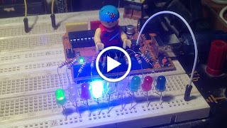
Actual Layout :

Procedure:
1. Use the same prototype as shown above
2. Run the Arduino Interface
3. Select File > New
4. Copy Code #7 above
5. Paste Code #7
6. Click File > Save
7. Click Verify
8. Click Upload
9. The four leds connected to pins 8 to 11 will count in binary (see binary table above)
Disclaimer: We shall not be liable for any loss or damage of whatever nature - direct, indirect, consequential, or otherwise - which may arise as a result of your use of any information on this website. However, if you are interested in using any of the projects for personal or educational purposes, please inform the author by email.
Public Domain Notice: Copyright (c) 2000. All rights reserved. This article is part of a book entitled iHackRobot. Copies are welcome to be shared or distributed publicly as long proper citations are observed. Please cite as follows: Biotronics: The Silver Species, Joey Lawsin, 1988, USA.
The Homotronics® and Homodruinos® logos are registered trademarks.
Copyright Biotronics© Inc. iHackRobot®. All Rights Reserved.
Patent Pending. 2000 © ®
==================================================================

Procedure:
1. Use the same prototype as shown above
2. Run the Arduino Interface
3. Select File > New
4. Copy Code #7 above
5. Paste Code #7
6. Click File > Save
7. Click Verify
8. Click Upload
9. The four leds connected to pins 8 to 11 will count in binary (see binary table above)
Disclaimer: We shall not be liable for any loss or damage of whatever nature - direct, indirect, consequential, or otherwise - which may arise as a result of your use of any information on this website. However, if you are interested in using any of the projects for personal or educational purposes, please inform the author by email.
Public Domain Notice: Copyright (c) 2000. All rights reserved. This article is part of a book entitled iHackRobot. Copies are welcome to be shared or distributed publicly as long proper citations are observed. Please cite as follows: Biotronics: The Silver Species, Joey Lawsin, 1988, USA.
==================================================================
Patent Pending. 2000 © ®
A L.A.W.S.I.N. Educational Production
No comments:
Post a Comment