How to build Knight Rider Lights Version on an Arduino:
by J.B. Wylzan
Project 4: Knight Rider Version
This project turns On 9 LEDs from left to right, then right to left continuously.
Hardware:
9 LEDs
9 resistors; 200 ohms
connecting wires
breadboard
Arduino Uno
Schematic Diagram:

Block Diagram:

Code # 4:
/*
iHackLab Chasing Lights (Knight Rider Version)
powered by Arduino
sketched by J.B. Wylzan
modified by Lawsinium
Turns on LEDs from left to right then right to left continuously.
This example code is public domain.
*/
// Setup pins 4 to 12
void setup()
{
pinMode(4, OUTPUT);
pinMode(5, OUTPUT);
pinMode(6, OUTPUT);
pinMode(7, OUTPUT);
pinMode(8, OUTPUT);
pinMode(9, OUTPUT);
pinMode(10, OUTPUT);
pinMode(11, OUTPUT);
pinMode(12, OUTPUT);
}
// Turns LEDs On and Off from left to right repeatedly,
void loop()
{
digitalWrite(4, HIGH); // turn the LED on
delay(100);
digitalWrite(4, LOW); // turn the LED off
digitalWrite(5, HIGH); // turn the LED on
delay(100);
digitalWrite(5, LOW); // turn the LED off
digitalWrite(6, HIGH); // turn the LED on
delay(100);
digitalWrite(6, LOW); // turn the LED off
digitalWrite(7, HIGH); // turn the LED on
delay(100);
digitalWrite(7, LOW); // turn the LED off
digitalWrite(8, HIGH); // turn the LED on
delay(100);
digitalWrite(8, LOW); // turn the LED off
digitalWrite(9, HIGH); // turn the LED on
delay(100);
digitalWrite(9, LOW); // turn the LED off
digitalWrite(10, HIGH); // turn the LED on
delay(100);
digitalWrite(10, LOW); // turn the LED off
digitalWrite(11, HIGH); // turn the LED on
delay(100);
digitalWrite(11, LOW); // turn the LED off
digitalWrite(12, HIGH); // turn the LED on
delay(100);
digitalWrite(12, LOW); // turn the LED off
digitalWrite(11, HIGH); // turn the LED on
delay(100);
digitalWrite(11, LOW); // turn the LED off
digitalWrite(10, HIGH); // turn the LED on
delay(100);
digitalWrite(10, LOW); // turn the LED off
digitalWrite(9, HIGH); // turn the LED on
delay(100);
digitalWrite(9, LOW); // turn the LED off
digitalWrite(8, HIGH); // turn the LED on
delay(100);
digitalWrite(8, LOW); // turn the LED off
digitalWrite(7, HIGH); // turn the LED on
delay(100);
digitalWrite(7, LOW); // turn the LED off
digitalWrite(6, HIGH); // turn the LED on
delay(100);
digitalWrite(6, LOW); // turn the LED off
digitalWrite(5, HIGH); // turn the LED on
delay(100);
digitalWrite(5, LOW); // turn the LED off
}
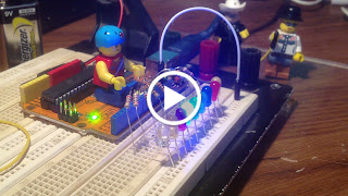
Actual Layout:

Procedure:
1. Use the same prototype as shown above
2. Run the Arduino Interface
3. Select File > New
4. Copy Code #4 above
5. Paste Code #4
6. Click File > Save
7. Click Verify
8. Click Upload
9. All 9 leds must turn On and Off from left to right and right to left continuously
Public Domain Notice: Copyright (c) 2000. All rights reserved. This article is part of a book entitled iHackRobot. Copies are welcome to be shared or distributed publicly as long proper citations are observed. Please cite as follows: Biotronics: The Silver Species, Joey Lawsin, 1988, USA.
==================================================================
Patent Pending. 2000 © ®
A L.A.W.S.I.N. Educational Production
Thanks alot. This was my first Arduino project. Keep up the good work.
ReplyDelete